State Diagram To Sequential Circuit Sequential Circuits
Circuit sequential state transition analysis diagrams Sequential carroll chapter8 uta State diagrams sequential circuit
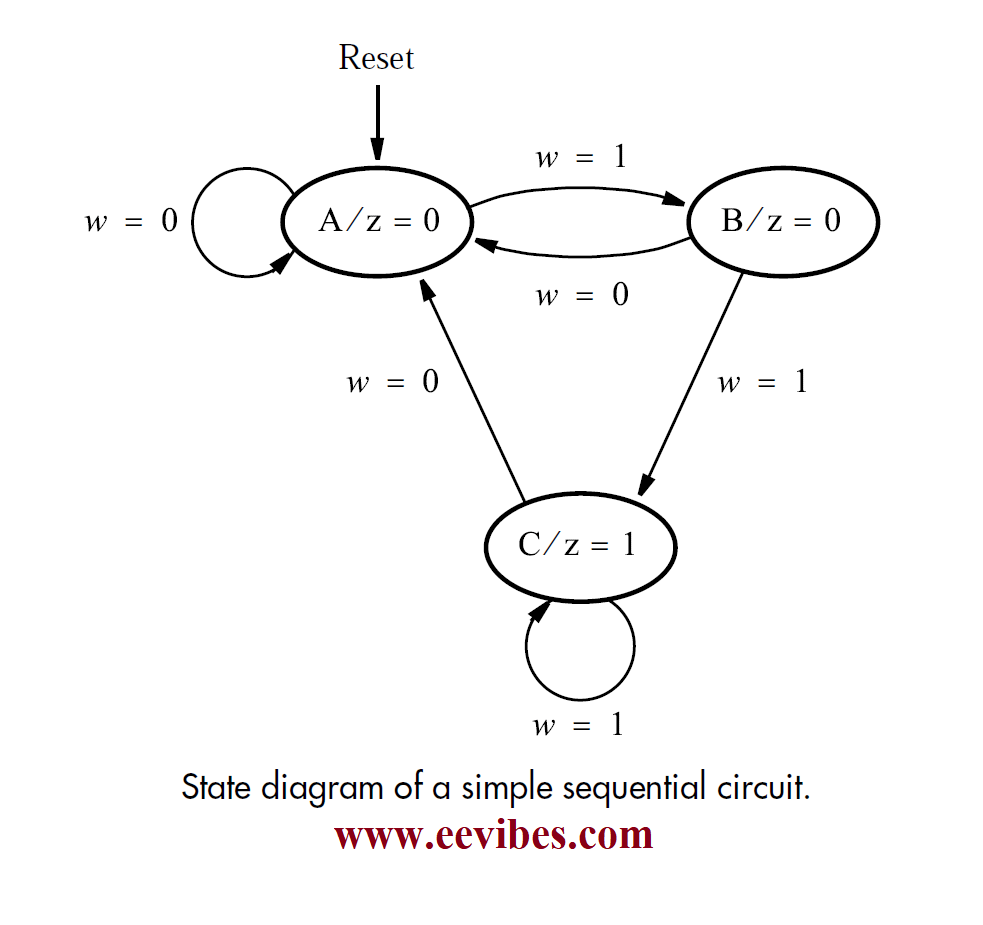
How to Draw State Diagram of Sequential Circuit? - Updated - EE-Vibes
Sequential combinational difference geeksforgeeks State diagram example of a sequential circuit, where states s 1 ; s 2 14+ t flip flop timing diagram
Solved the state diagram for a sequential circuit in shown
Design the synchronous sequential circuit for state diagram electricalDesign sequential circuit from state diagram using jk flip flop Solved draw the state diagram of a sequential circuit, whichSolved the state diagram of a sequential circuit is given as.
State diagram for sequential circuit by sleepnearme[diagram] bias t circuit diagram State diagram sequential circuitDesign sequential circuit state diagram.

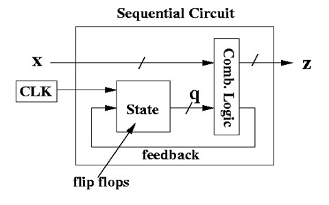
Sequential circuits state diagram
State diagram sequential circuitsSolved a state diagram of a sequential circuit is given in Difference between combinational and sequential circuitSequential flip specified flops jk ckt.
Sequential circuitsMoore sequential circuit state diagrams Sequential circuit design state diagramHow to draw state diagram of sequential circuit?.

Solved the state diagram of a sequential circuit is given as
Sequence detector state diagram sequential has circuits states figure output transition line edwardbosworth htm labeled five note desired lines eachSequential circuit state diagram Solved design the sequential circuit specified by the stateState sequential circuit diagram ppt powerpoint presentation.
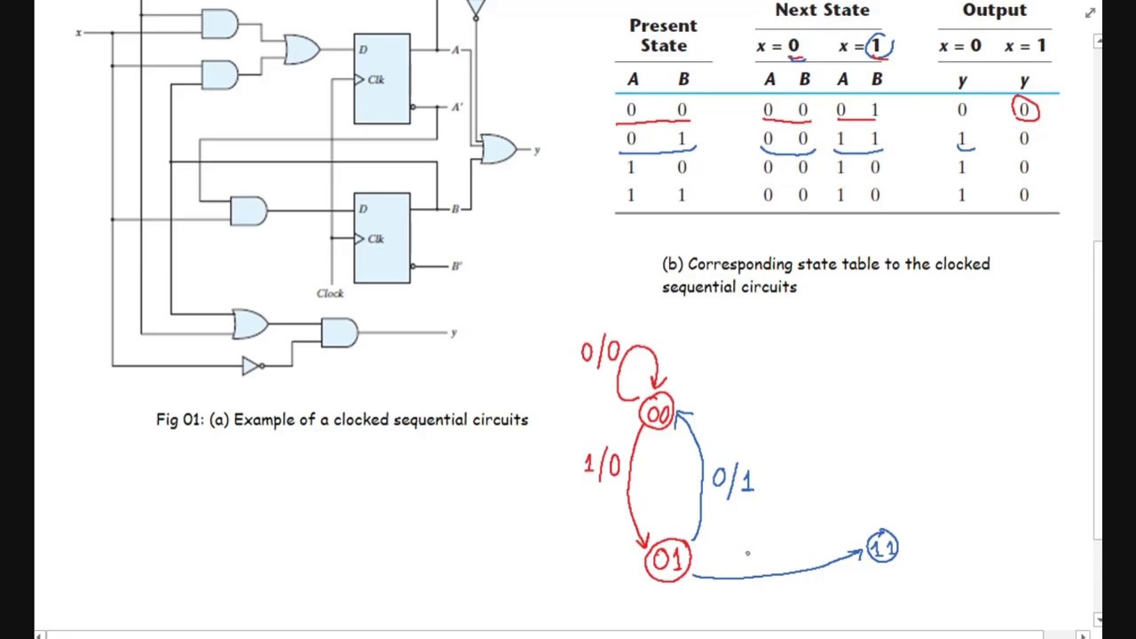
Analysis of sequential circuit state diagrams -- example 8.3How to draw state diagram of sequential circuit? Combinational circuits & sequential circuit – ahirlabsState diagram sequential circuits.

Solved design a sequential circuit for the following
The state diagram for a sequential circuit appears in figure 4 aboveShow solved state circuit sequential diagram transcribed problem text been has Solved below is a state diagram for a sequential circuit. 0Solved the following is a state diagram of a sequential.
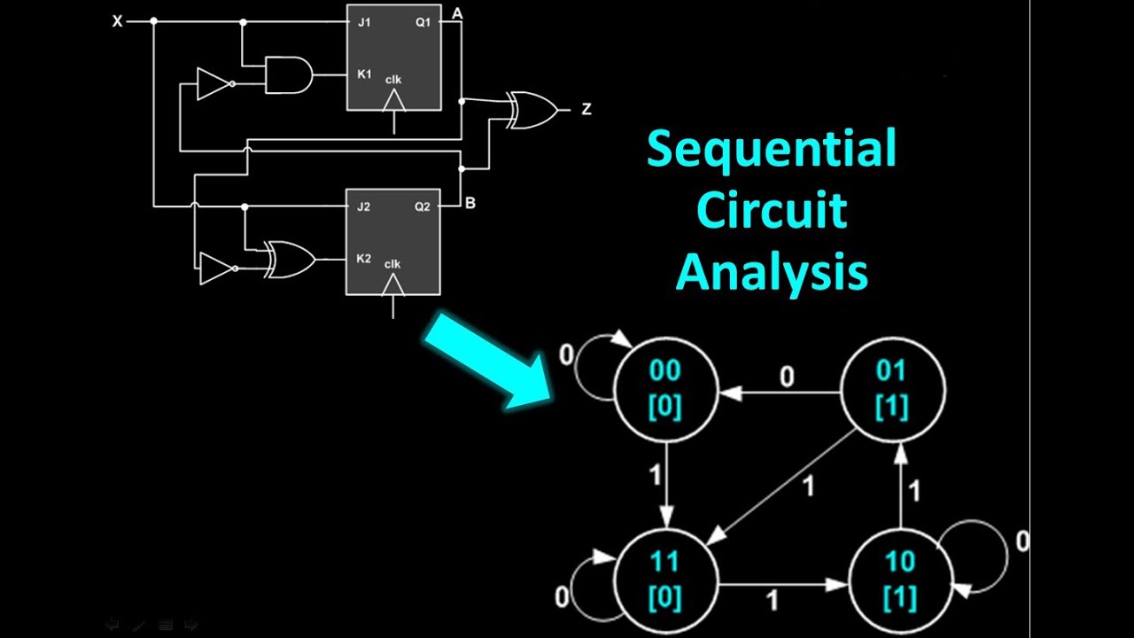
Sequential circuit circuits combinational diagram difference inputHow to draw state diagram of sequential circuit? State diagram of sequential circuitSequential circuit analysis.